Wiring Diagrams
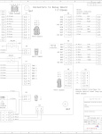
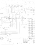
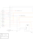
Carrier 98-62158 Wiring Diagram
EM-17, CM-5, O5G
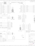
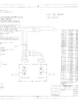
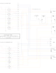
Carrier 98-62278 Wiring Diagram
EM-17 w/Heat, R134a
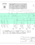
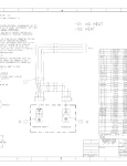
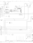
Carrier 98-62323 Wiring Diagram
AC-862/863 Uses 98-62018-00
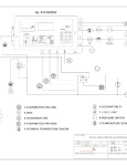
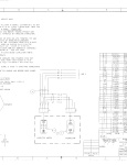
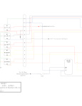
Carrier 98-62338 Wiring Diagram
EM w/CM AC-553T "GSA" Uses 91-62022-00
Carrier 98-62439 Wiring Diagram
EM w/CM (3 Speed) Uses 91-62040-00
Carrier 98-62652 Wiring Diagram
Uses 91-62040-00 and 91-62046-00
Carrier 98-62678 Wiring Diagram
EM-17 / KR-4 / O5G
Carrier 98-62718 Wiring Diagram
EM-3,(2)EM, KR-4, O5G, 24V, VAR SPD Uses 91-62069-00
Carrier 98-62723_A Wiring Diagram
EM-9 KR-4 24V, Uses 2 x 91-62067-00
Carrier 98-62731 Wiring Diagram
(2) EM-1, (1) EM-7, KR-4, O5G, 24V, VAR SPD Uses 91-62069-00
Carrier 98-62749 Wiring Diagram
(1) EM-1, (1) CM, 12V, TempCon Control Uses 91-62022-00
Carrier 98-62754 Wiring Diagram
(2) IW-1, (1) KR-4, (2) Comp, 12V Uses 2 x 91-62040-00
Carrier 98-62877 Wiring Diagram
(1) EM-1, (1) CM, (1) EM-7, TempCon Control Uses 91-62046-00
Carrier 98-63152 Wiring Diagram
DC12175 Cool Only System, (HPS INLINE)
Carrier 98-63163 Wiring Diagram
Supplemental for KR-4D Applications Uses 2 x 91-62046-00 and 91-62069-00
Carrier 98-(67037,63176,63135) Wiring Diagrams
AC-430, 12V
Espar 88-50-40-00098-00 Wiring Diagram
(OBSOLETE) Use 88-50-40-00294-00
Espar 88-50-40-00294-00T1 Wiring Diagram
Espar AC-353G4-II+III Narrow with KL01 Controller, 12V, Single Loop, Add On Clutch Relay with THCU1023E timer installed.

Espar 88-50-40-00294-00 Wiring Diagram
Espar AC-353G4-II+III Narrow with KL01 Controller, 12V, Single Loop, Add On Clutch Relay installed. To be used in place of 88-50-40-00098-00

Espar 88-50-40-00309-00T1 Wiring Diagram
Espar AC-353G4-II+III Narrow with KL01 Controller, 12V, Dual Loop, Add On Clutch Relay with THCU1023E timer installed
Espar 88-50-40-00309-00 Wiring Diagram
Espar AC-353G4-II+III Narrow with KL01 Controller, 12V, Dual Loop

Espar 88-50-40-00310-00 Wiring Diagram
Espar AC353G4 III Narrow with KL01 Controller, 24V, Single Loop, All Brushless
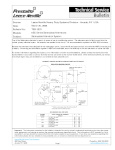
Ford/Roush BB-01 Wiring Diagram
Diagram showing Roush side of A/C clutch circuit from where TransArctic makes it's connection.
ID-10 w/ Plenum & Door
ACT ID-10 In Dash with Plenum and Door
MCC Y66-00002 Wiring Diagram
Uses 2 x Y25-00003-00
MCC Y66-00008 Wiring Diagram
EM w/CM AC-553 Uses Y25-00012-00
MCC Y66-00010 Wiring Diagram
3 EM w / KR-4, TempCon Control Uses Y25-00012-00 and Y25-00013-00
MCC Y66-00011 Wiring Diagram
(1) EM-1, (1) CM, 12V, TempCon Control Uses Y25-00012-00
MCC Y66-00012 Wiring Diagram
(2) EM, GIV/ EM, GV/ EM w/KR-4, 3 SPD Uses Y25-00012-00 and Y25-00013-00
MCC Y66-00017 Wiring Diagram
(1) EM, (1) CM, (1) EM-7, TempCon Control (or 3 Speed Switch ) Uses Y25-00013-00
MCC Y66-00029-M1 Wiring Diagram
ECO353 Single Loop Manual Control with Off-Hi-Lo Toggle
MCC Y66-00029 Wiring Diagram
MCC ECO353, Single Loop, 12/24V w/ Enviromate Controller (Use in place of Y66-00036 for troubleshooting)
MCC Y66-00036 ECO353 Electrical Reference
MCC ECO353 SL Electrical Reference diagram, see Y66-00029 for troubleshooting
MCC Y66-00055 Wiring Diagram
EM-17 with K430 Condenser and 05G Compressor
MCC Y66-00059 Wiring Diagram
3 Evaps w/ Dual Loop K430
MCC Y66-00060 Wiring Diagram
2 EM w/ K430 Condenser (2 or 3 Fan) - 3 Speed Control Uses Y25-00012-00 Panel
MCC Y66-0089 Wiring Diagram
Wiring Diagram for the Eco 8 or Eco 10 Rooftop 12V Contains Relay Board 35-0701
Spheros 20 000 001A-TA001 Wiring Diagram
20000001A_CC335 12V _GLOBUS RELAY BOARD (D3FE GSA)
Spheros 20 000 001A Wiring Diagram
20000001A_CC335 12V _GLOBUS RELAY BOARD
Spheros 20 000 002A Wiring Diagram
20000002A Arcticsphere Split System, Dual Evaporator, Condensers, Single Compressor
Spheros 20 000 004A Wiring Diagram
20000004A Arcticsphere Split System
Spheros 20 000 006A Wiring Diagram
20000006A Relay Control 11117844A and Manual Control Panel 11116024A Schematic, 2-19-13
Spheros 20 000 007A Wiring Diagram
20000007A Digital Control Panel 550255A Electrical Schematic, 2-19-13
Spheros 20 000 008A Wiring Daigram
20000008A Relay Control 007-00019-001Relay and Fuse Location, 2-19-13
Spheros 20 000 009A Wiring Diagram
20000009A Relay Control 007-00019-001 With 550255A Digital Control Panel, 2-19-13
Spheros 20 000 019A Wiring Diagram
20000019A Arcticsphere Split System RC320 With IW200
Spheros 20 000 027A Wiring Diagram
20000027A Arcticsphere Split System with High Speed Fan Relays
Spheros 20 000 027B-TAG Wiring Diagram
20000027B Arcticsphere Split System with High Speed Fan Relays
Spheros 20 000 027B Wiring Diagram
20000027B Arcticsphere Split System with High Speed Fan Relays
Spheros 20 000 035A Wiring Diagram
20000035A - CC355_SL_24V Globus
Spheros 20 000 036A Wiring Diagram
20000036A Arcticsphere Split System, 2 Evaporators v4
Spheros 20 000 037A Wiring Diagram
20 000 037A Arcticsphere Split System with Globus Digital Control v1 Sheet_1
Spheros 20 000 039A Wiring Diagram
20000039A CC335 DL/SL 12V with Wurth SL Relay Board
Trans/Air Wiring Diagram 5031159
Wiring Diagram for T/A 986, Basic II, 3 Speed, Rotary Thermostat, Transit Comp, Rear Engine
Trans/Air Wiring Diagram 5031516
Wiring Diagram for adding on a 2nd 12V Alternator - Leece Neville 8SC with Power Isolator
Trans/Air Wiring Diagram 503621
Trans/Air 503621, TA-17 Installation Diagram, 24V, Conventional
Trans/Air Wiring Diagram 503688
T/A-17 Conventional, 2 Speed, NGR Rocker Switch 24V
Trans/Air Wiring Diagram 503820
24V Batteryless Alternator Kit

TransArctic GS-01 Wiring Diagram
EM-7 Tie - In on a Thomas Bus using Y25-00031-00
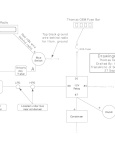
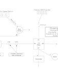
TransArctic GS-02 Wiring Diagram
Thomas C2 Dash tie in to existing evaporator using Y25-00012-00 panel
TransArctic KH-10 Wiring Diagram
TransArctic KDA00002 Dash using Toggle Switches
TransArctic KH-13 Wiring Diagram
ACT EV2/CR3 system using MCC Y25-00012-00 panel
TransArctic KH-14 Wiring Diagram
3 MCC Evaporators 2 MCC Condensers w/ Single compressor
TransArctic KH-15 Wiring Diagram
Standalone KDA00006 system w/ condenser and compressor
TransArctic KH-16 Wiring Diagram
ACT Dash Cool Only Standalone
TransArctic KH-17 Wiring Diagram
ACT Dash Heat/Cool Standalone
TransArctic KH-18 Wiring Diagram
(2) FM55 with R120 condenser -or- (2) SC4 condensers and single compressor
TransArctic KH-19 Wiring Diagram
TA77/R90 - TA93x2/R120 - TM65 Compressor
TransArctic KH-20A Wiring Diagram
Thomas C2 with TransArctic KDA00004 In Dash and 2 FAN CM-2
TransArctic KH-20 Wiring Diagram
Thomas C2 with TransArctic KDA00004 In Dash and 2 FAN CM-2
TransArctic KH-21 Wiring Diagram
2 or 3 ACT evaporators with 2 Condensers and F400 compressor
TransArctic KH-22 Wiring Diagram
"Classic" Dual Loop EM3 with 2 EMs 2 SC4 and TM65 Compressor
TransArctic KH-23 Wiring Diagram
3 TransAir Evaporators with R120 or 2 R90 and Single Compressor using MCC Electrical
TransArctic KH-24 Wiring Diagram
"Classic" Dual Loop EM3 with 2 EMs K430 and TM55/65 Compressor
TransArctic KH-25 Wiring Diagram
G5 EM3 w/ IW or EM and K430 w/ 2 TM21
TransArctic KH-27 Wiring Diagram
Classic DL EM3 and IW1 with DL K430 and 2 TM21s
TransArctic KH-28 Wiring Diagram
Four EM1's with CM5 and 05G - 24V w/ 12V controls
TransArctic KH-29 Wiring Diagram
TA77 - 2x TA93 - 2x SC4 with TM65
TransArctic KH-32 Wiring Diagram
(2)IW/CM with single TEMPCON control and TM55 compressor
TransArctic KH-62718 Wiring Diagram
Used in place of 98-62718 when not using O5G compressor
TransArctic KH-8KS Wiring Diagram
GSA Enviromate w/ Bitzer F400